solar panel installation diagram pdf
Understanding Solar Panel Wiring Diagrams
Solar panel wiring diagrams are crucial for successful installations. These visual guides illustrate how panels, inverters, charge controllers, and batteries interconnect, ensuring efficient electricity flow. Understanding these diagrams is essential for safe and effective solar system setup. Downloadable PDFs often provide detailed illustrations.
Basic Components and Their Interconnections
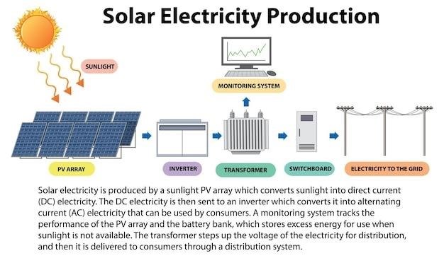
A typical solar panel system comprises several key components⁚ solar panels themselves, which convert sunlight into DC electricity; a charge controller, regulating the flow of electricity from the panels to the batteries; and batteries, storing the energy generated for later use. An inverter converts the stored DC electricity into AC power suitable for household appliances. Wiring diagrams illustrate how these components connect. Solar panels are wired in series or parallel configurations (discussed later) to achieve desired voltage and current outputs. The charge controller connects to the panels’ positive and negative terminals, then to the battery’s terminals. The inverter connects to the batteries, transforming DC to AC for household use. Proper interconnection ensures optimal system performance and safety. Understanding these connections is vital before starting any installation.
Series vs. Parallel Connections⁚ Advantages and Disadvantages
Solar panel wiring diagrams frequently show series or parallel connections, each with distinct advantages and disadvantages. Series connections link panels positive to negative, increasing voltage while maintaining amperage. This is efficient for long distances to the charge controller but a single panel failure impacts the entire string. Parallel connections link all positive and negative terminals together separately, increasing amperage while maintaining voltage. This offers redundancy; one panel failure doesn’t stop the system, but requires thicker wiring due to higher current. Choosing between series and parallel depends on system requirements and desired voltage/current output. Diagrams clearly illustrate which configuration is used, aiding in understanding system design and troubleshooting. The choice influences wire gauge and overall system efficiency. Careful consideration is necessary to optimize performance and safety.

Different Solar Panel System Configurations
Solar panel system configurations vary widely, impacting wiring diagrams. Grid-tied systems connect directly to the utility grid, while off-grid systems utilize batteries for energy storage. Understanding these differences is key to interpreting installation diagrams accurately.
Grid-Tied Systems⁚ Wiring Diagrams and Considerations
Grid-tied solar panel systems offer a straightforward approach to harnessing solar energy. Their wiring diagrams typically show a relatively simple connection between solar panels, a combiner box (often consolidating multiple strings of panels), and a string inverter. This inverter converts the direct current (DC) electricity generated by the panels into alternating current (AC) compatible with your home’s electrical system. The AC power then flows directly to your home’s electrical panel. A crucial consideration is the system’s interconnection with the utility grid; this requires adherence to specific regulations and necessitates a detailed understanding of local electrical codes. Proper grounding and overcurrent protection are paramount for safety and compliance. Installation diagrams for grid-tied systems will clearly indicate the connection points for the main breaker, the inverter’s AC output, and the grounding system. It is vital to consult professional installers or relevant guidelines to ensure safe and compliant installations.
Off-Grid Systems⁚ Wiring Diagrams and Battery Integration
Off-grid solar systems, unlike grid-tied systems, operate independently of the utility grid. Their wiring diagrams are more complex, reflecting the inclusion of battery banks for energy storage. These diagrams illustrate the connections between solar panels, a charge controller (regulating the flow of electricity to the batteries), the battery bank itself, and an inverter (converting DC from the batteries to usable AC power). Proper sizing of the battery bank is crucial for meeting energy demands, and the diagrams will show the parallel or series connections used to achieve the desired voltage and capacity. A crucial consideration is the inclusion of safety features like fuses and circuit breakers to protect against overloads and short circuits. Detailed diagrams will show the placement of these safety components and the proper wiring procedures. Careful planning and attention to detail are essential for efficient and safe operation of an off-grid system, with diagrams acting as essential visual guides.
Detailed Solar Panel Installation Diagrams⁚ PDFs
Many online resources offer downloadable PDF diagrams detailing solar panel installations. These PDFs provide comprehensive visual guides, simplifying the installation process. Understanding diagram symbols is crucial for accurate system setup.
Locating and Downloading Relevant Diagrams
Finding suitable solar panel installation diagrams in PDF format often involves searching online through manufacturer websites, renewable energy blogs, or specialized online marketplaces. Many manufacturers provide detailed diagrams specific to their products, ensuring compatibility and ease of installation. These diagrams frequently include system schematics, component layouts, and wiring configurations. Searching for terms such as “solar panel wiring diagram PDF,” “solar panel installation guide PDF,” or “photovoltaic system schematic PDF” will yield numerous results. Always verify the source’s credibility and ensure the diagram aligns with your specific system components before downloading and using it. Remember to check for high-resolution versions for better readability and clarity. Some websites offer free downloads, while others may require registration or a small fee for access to premium or detailed documentation.
Interpreting Diagram Symbols and Conventions
Solar panel installation diagrams utilize standardized symbols and conventions for clear communication. Understanding these symbols is crucial for accurate interpretation. Common symbols represent solar panels (often depicted as rectangles with plus and minus signs), batteries (shown as parallel lines), inverters (represented by a stylized wave), charge controllers (frequently depicted as a square with input and output arrows), and various wiring components. Line thickness and color often indicate wire gauge and voltage levels. Arrows illustrate the direction of current flow. Labels and annotations provide further clarification on component specifications, such as voltage, amperage, and wattage. Familiarity with these conventions ensures correct component identification and understanding of the system’s electrical pathways. Referencing a legend or key within the diagram itself is essential for unambiguous interpretation. Online resources and tutorials can also aid in deciphering any unfamiliar symbols or conventions.

Safety Precautions and Best Practices
Always disconnect power before working on any solar system components. Use appropriate personal protective equipment (PPE), including gloves and safety glasses. Follow all local electrical codes and regulations. Proper grounding and wiring techniques are crucial for safety.
Proper Wiring Techniques to Avoid Hazards
Incorrect wiring can lead to system failure, fire, or electric shock. Always use appropriately sized wire for the amperage and voltage. Ensure all connections are secure and properly insulated to prevent shorts. Use the correct connectors and lugs for each wire gauge and terminal type. Never mix different wire types or gauges in the same circuit unless specifically allowed by code. Consult the manufacturer’s instructions for specific wiring diagrams and recommendations. Proper grounding is vital; ensure a solid earth ground connection. Double-check all connections before energizing the system. If unsure, consult a qualified electrician. Regularly inspect wiring for damage or loose connections. Replace damaged wiring immediately. Proper labeling of wires enhances troubleshooting and maintenance.